Making a buck converter
Background
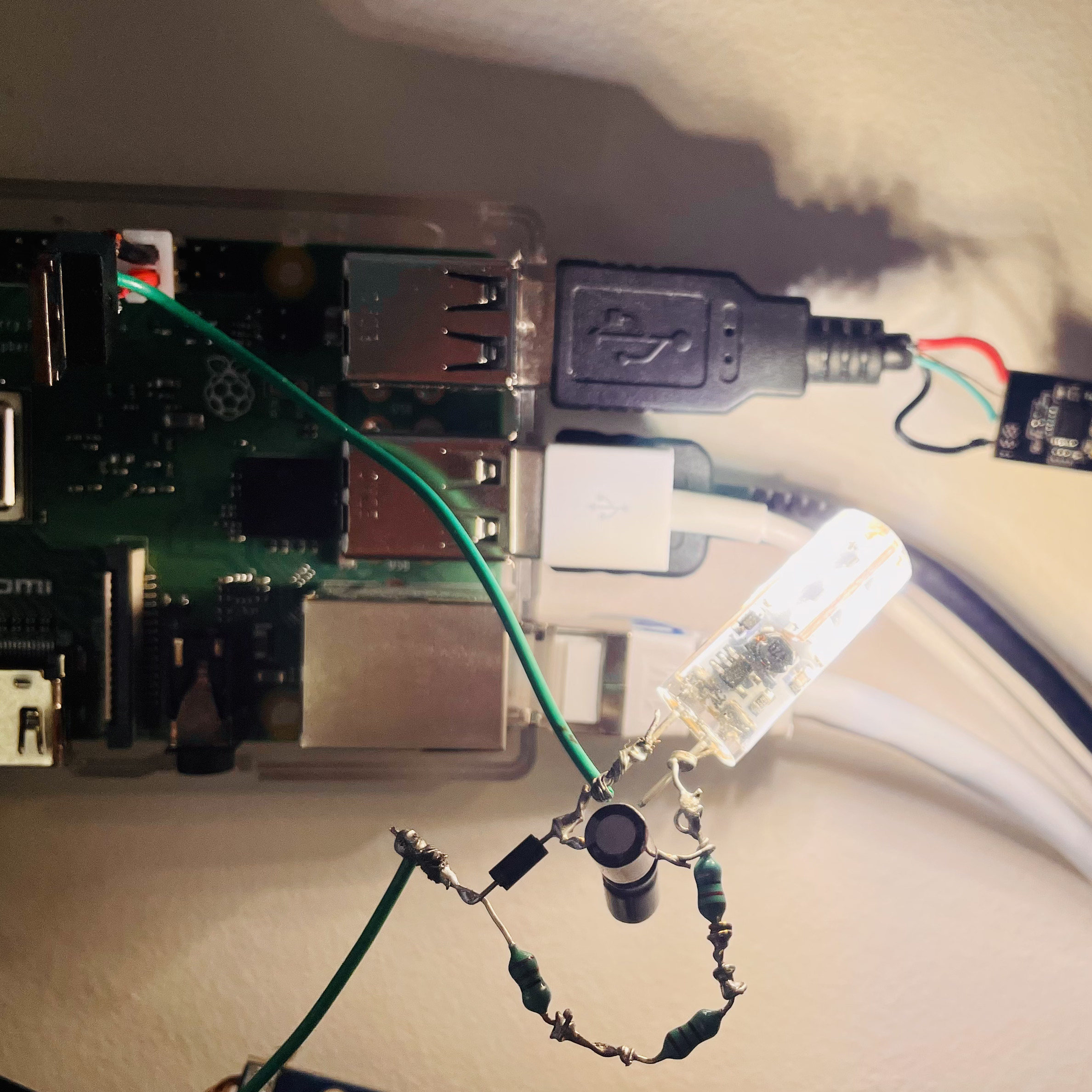
I have a “smart” control system in my room. Actually, it is quite dumb: it is just a Raspberry Pi 3B+ connected to a beefy power supply. The Pi itself is connected to a temperature probe to monitor my room temperature, and a Ubiquiti UAP-LR I dug out from the IT dumpster powered by a homemade passive POE cable to provide tunnelled Wi-Fi. The Pi also acts as a router.
Last year, I had a solid-state relay (provided by my physics teacher) in the light fixture that I could use to control the light. Later, I moved the relay to other projects for the house. So that I still have a “smart” light, I put up a 20V light bulb controlled by the Pi via a transistor. I tried to dim it like an ordinary LED by outputting a PWM signal, but it did not work. I did not understand it back then, so I replaced the transistor with a spare ESC I had, which did not help either. Considering that this light bulb is designed to operate from 10V to 35V and there is a whole bunch of circuits inside, this is probably reasonable: it may have its own stabilizing circuitry inside.
Earlier this school year, I decided to apply my RF knowledge and do something to my little light. I put an aluminum capacitor across it and a resistor in series with it: forming an RC filter.

It turns out that the resistor can get quite hot, although I already used four bigger resistors in parallel. The voltage drop across the resistors was also significant, leaving the light never completely on. Well, at least the system is dimming now.
Then one day, when I was adjusting another power supply, I realized I was making a buck converter unknowingly! Realizing that, I moved on to design a real buck converter so as to make my place look nicer.
Design
Most of the simple buck circuits online put the switch on the positive side of the circuit. It may make sense in other common use cases, but definitely not here. My Pi and the 20V power supply share the same reference, so I would either need a driver circuit or fry my Pi.
Well, IB students are critical thinkers. We won’t be puzzled by this: I designed my own circuit with a common ground.

The N-channel MOSFET in the circuit, RJK1536DPN, was taken from a dead EV charger in the dumpster as well. Initially, I tried to work out all the parameters with the loop rule and the junction rule. Well, I did make some progress, but I ended up using an LTSpice simulation to iterate the design faster. Now I understand the advantage of the “conventional” design: in my version, the load has a floating reference. However, this should not matter for my little light bulb.
Reflection
There is still a glitch with this design. When the duty cycle is more than 41%, the voltage does not seem to change much. That’s probably because the light does not consume enough charge from the capacitor. In other words, I want it to operate in continuous mode, where the output voltage is proportional to the duty cycle. However, the load is too light, so the converter is in discontinuous mode. It is just a light anyways, I do not mind if the rise/fall time is larger, so I will probably adjust the inductors and capacitors. In the meantime, I will compensate for the nonlinearity on the software side.
Nonetheless, this is my first buck converter made by hand, and I am glad to see it work.
Update (2022-11-23)
I found some extra time during the power outage and experimented with the response curve of my creation. At 100kHz’s switching frequency and 19.90V’s input, here is the result:

Note: The circuit seems to resonate at the ducy cycle of 420000. After the duty cycle is below 80000, the load light turns off.
I guess one thing I can do is to fit a curve on the operation region and find a way to give linear output stepping.
Update (2022-11-30)
Here is the new dimmer:
def intensity_to_dcycle(perceived_intensity: float) -> int:
    # Logarithmic dimming
    real_intensity = e ** (perceived_intensity * log(101, e) / 100) - 1
    # Linearly scale to voltage
    voltage = real_intensity * (19.2 - 7.845)/100 + 7.845
    # Piecewise fit
    if 7.845 < voltage <= 9.275:
        return int(281970 * (-7.664 + voltage))
    if 9.275 < voltage <= 13.75:
        return int(26520 * (6.959 + voltage))
    if 13.75 < voltage <= 16.88:
        return int(49485 * (-2.529 + voltage))
    if 16.88 < voltage <= 19.2:
        return min(int(21692 * (26.90 + voltage)), 1000000)
    # Out of range
    return 0